
Diagnosing Modbus Communication Errors: Timeouts, Addressing, Framing, and Data Formats
A systematic Modbus RTU workflow for separating timeouts, exception codes, framing faults, addressing errors, gateway delays, and incorrect data formats.
A failed Modbus link shows up as a timeout, an exception code from the slave, garbage values in the register map, or silence. Every one of those symptoms has several possible causes. A timeout can mean a wiring fault, a baud mismatch, the wrong slave ID, a busy slave, or a gateway forwarding to a dead device.
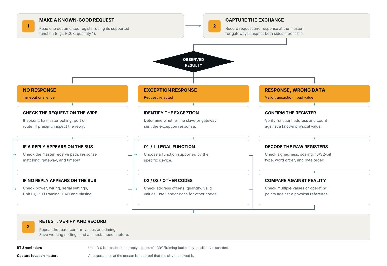
Classify the failure before touching anything, since the three failure classes need different debugging approaches. In the first class, the master gets no response at all. The frame never got through, so the problem lies in the physical layer, addressing, framing, or a CRC that was discarded silently. In the second, the slave returns an exception response. The frame arrived, but the request itself was faulty, perhaps an unsupported function code or an out-of-range register address. The third class is subtler. Transactions complete cleanly but the data is wrong, usually because master and slave disagree on word order or signedness.
Misclassify and you can waste hours re-terminating serial lines when the actual fault is a data format. This is why a serial sniffer is the fastest classification tool. It sees every frame on the wire, including the ones Modbus’s error handling never reports to the master. A silent CRC failure looks identical to a wiring fault from the master’s side, and the exception mechanism only fires when a frame actually reaches a slave.
No Response When the Slave Never Answers
Start with the physical layer, because a frame that never reaches the slave produces exactly this symptom.
Check wiring and termination first, then confirm the devices share a reference potential. One caveat on RS-485 A/B line swaps is that transceivers vary and some do not work with inverted pairs. An A/B swap may not always result in a clean timeout. It can also cause framing errors. Electrical problems that track with cable length, node count, or ground potential between devices usually come down to biasing, termination, or a missing reference. That reference layer is worth investigating on its own, apart from the protocol.
Every device on an RTU line must agree on baud rate, parity, and stop bits. A mismatch means the slave either sees nothing intelligible or never sees the frame as addressed to it. The slave ID is worth checking as well, since device 0 is broadcast in RTU and some tools silently renumber or use a different convention than the vendor’s documentation.
Silence delimits RTU frames, not characters. A frame must have at least 3.5 character times of inactivity (t3.5) preceding and following it. A gap of more than 1.5 character times inside a frame makes the receiver discard it as incomplete. Timing jitter landing at the wrong moment splits a frame in two, and what the receiver reports looks like a random CRC failure, typically only on marginal installations.
An RTU character is 11 bits long, counting the start bit, 8 data bits, the parity bit, and the stop bit. Below 19200 bps, the timers derive from character time. Above that threshold the spec does not derive them at all. It fixes 750 µs (t1.5) and 1.75 milliseconds (t3.5). Strict timer enforcement at high baud rates is expensive in interrupt load, and the spec acknowledges this, which is why some slave implementations cut corners on it. Framing problems get worse at higher baud rates. The timing tolerances in the silicon stay the same, but the intervals they have to hit shrink.
| Baud rate | Character time (11 bits) | t1.5 (1.5 char) | t3.5 (3.5 char) |
|---|---|---|---|
| 2400 | 4.6 ms | 6.9 ms | 16 ms |
| 9600 | 1.15 ms | 1.72 ms | 4.0 ms |
| 19200 | 573 µs | 0.86 ms | 2.0 ms |
| >19200 | — | 750 µs (fixed) | 1.75 ms (fixed) |
A CRC failure can produce a timeout with nothing on the wire to explain it. RTU slaves only check the CRC at end-of-frame. The slave deletes a bad frame without responding. All the master sees is the timeout, so a discarded frame is indistinguishable from a dead device. Intermittent timeouts with no exception codes in the log point at marginal signal integrity. The slave is discarding frames at CRC check. This is the situation that justifies a sniffer on the bus. It shows whether the slave received the frame the master thinks timed out.
Exception Responses: When the Request Is Invalid
An exception response tells you the frame arrived intact and passed CRC. The slave refused the request anyway. The exception code says what the slave objected to.
Exception 01 (Illegal Function) means the device has no handler for the function code you sent. Many devices implement only part of the protocol. Some lack function 15/16 for multi-write, and others have no write support at all. Check the device’s documented function codes against what your master sends.
Exception 02 (Illegal Data Address) means the register range you requested doesn’t exist on the slave. The most common cause is the addressing off-by-one.
In the protocol itself, register addresses start at 0. Most vendor documentation and HMI software use 1-based numbering with a prefix. “Holding register 40101” in vendor documentation usually maps to protocol address 100, but some vendors use 101. A mismatch between the two returns exception 02 when the master asks for 101 while the device’s protocol address is 100. Reading an adjacent register may go through without error. The worked case is that the doc says 40101, the master requests protocol address 100 and gets exception 02, and trying 101 succeeds. To pin down the vendor’s convention, read registers one at a time and check each result against a value you already know.
Exception 03 (Illegal Data Value) covers requests whose value or structure doesn’t fit that register. Two usual triggers are a read that asks for the wrong number of registers, or a write of a value the device won’t accept.
Register counts have a ceiling. The protocol allows function 03 to read up to 125 registers, but many devices accept far fewer. Exceed what the device allows and you’ll get an exception back, usually 02 or 03. Vendors differ on which code they return here, so the exact code tells you more about the device’s implementation than about the request itself.
Wrong Data, Clean Transactions
The transactions complete cleanly and exception-free, yet the value is nonsense. The fault lies in data interpretation, not the link. A temperature reading of 1.7E+38 is the classic signature.
The usual cause is word-order swap in multi-register values. Modbus transmits 16-bit registers, and a 32-bit float spans two registers, with no protocol-level convention for which register comes first. Read a big-endian float as little-endian, or the other way around, and you get a number that looks plausible but is wildly wrong. In practice, read the pair both ways and keep whichever word order gives a value consistent with the physical quantity. Byte order within registers can also vary, but word order is where most cases resolve.
Signedness is the second common trap. Reading a signed 16-bit value as unsigned turns −1 into 65535. This produces wrong-but-bounded values rather than garbage, which helps distinguish it from a word-swap problem.
Gateways and Stacked Timeouts
A TCP master polling through a gateway to RTU slaves adds a second timeout into the path. If the gateway’s own timeout to the client is shorter than the RTU slave’s response time, which is common with slow slaves or gateways servicing many units, the master can time out even though the slave eventually responds. The exact failure signature (gateway exception, client timeout, or response misalignment) varies by implementation. The practical check is whether a device that times out through the gateway responds when polled directly on the serial side.
A Diagnostic Sequence
Further Reading
- Modbus Organization, MODBUS over Serial Line Specification and Implementation Guide V1.02 — RTU/ASCII transmission modes, frame delimiting, and the t1.5/t3.5 timing rules cited throughout this article.
- Modbus Organization, MODBUS Application Protocol Specification V1.1b3 — Function codes, register quantity limits, and the full exception code table.
- Modbus Organization, Specifications and Implementation Guides — Index of current protocol specifications and related documents.