
Integrating a New PLC With an Existing Brownfield Control System
A practical guide to brownfield PLC integration through PLC coexistence planning, field I/O verification, interface contracts, shadow-mode testing, staged cutover, and rollback.
Most brownfield PLC projects replace a controller with one from a different brand or generation, with the maintenance window measured in hours. The program itself is rarely what sinks the schedule. What does is the coexistence decision you make first and the field I/O inventory, which almost always takes longer than you budgeted for.
Coexistence Options
A PLC nearing documented end of life, or one with a history of failures, may justify replacement. If it still runs reliably and remains supported, replacing it can add project risk without a clear operational benefit.
Spare I/O capacity is useful only if there is a practical way to connect the field devices. In a parallel arrangement, the new controller needs its own field connections. This can mean adding interposing terminals or relays, or running duplicate cables. The work can cost more when marshaling cabinets are full or cable trays are crowded.
When both controllers natively support a common protocol, bridging costs less. For example, connecting a legacy system that supports only Modbus RTU to a new controller that uses Ethernet requires conversion hardware.
The plant’s available shutdown window also constrains the choice. A full week of shutdown may allow a complete replacement in one cutover. For a plant operating across three shifts, a staged cutover may be needed, with both systems running during commissioning. In that case, a parallel or bridge architecture may be more suitable.
A decision flow can show how these factors affect the choice.
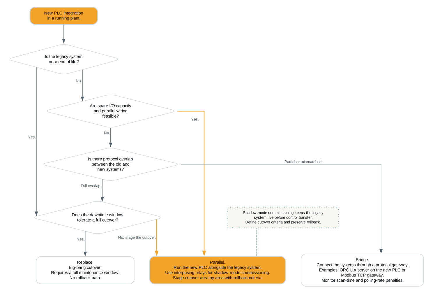
The right choice depends on the constraints at the plant. Support life gets overrated. A legacy controller may have five years of support remaining, but that does not help if all its spare I/O slots are occupied. Sometimes, fitting new I/O in the old panel takes more engineering time than installing a new panel beside it. In that case, full replacement may be worth the cutover risk. The honest way to run this decision is to score each factor for your specific plant and let the worst constraint pick the path.
After cutover, replacement leaves you with one controller and one codebase. The trade-off is the cutover window itself, where all the risk is concentrated. In parallel operation, the new PLC is installed beside the old one, and circuits move over one at a time. Risk is spread across the cutover instead of concentrated in one window, and the price is roughly double the wiring. It also requires decommissioning the old system promptly. If both systems remain in service for too long, each panel may control part of the process, leaving operators unsure which one controls what. It’s the usual brownfield route, because parallel operation is what makes shadow-mode commissioning and a physical rollback path possible.
With a bridge, each system can retain its own I/O. Wiring stays minimal, but the extra data hop alters scan-time and data-freshness behavior. That’s covered below.
Field I/O Inventory
Tracing a signal from the field device through junction boxes and marshaling to its terminal can take longer than writing the new PLC program. For every signal the new controller will own, trace it from the field device through junction boxes and marshaling to a terminal. Check the circuit against the drawing and correct the drawing where the two disagree, then record the actual signal level and scaling. Some drawings are missing or out of date. Changes made during breakdowns may not have been recorded.
Check for signal-level mismatches and undocumented interlocks. A common mismatch is legacy I/O that is 24 VDC sinking (NPN-style field wiring), while the new card you specified expects sourcing inputs. Nothing in the documentation flags this because the legacy drawings just say “24 VDC.” You find it during checkout when the first input won’t pull in. The usual fix is interposing relays, and every relay adds a socket, panel space, and a line item on the terminal schedule. If inventory finds the mismatch early, include the relays in the purchase order; if it surfaces during commissioning, the fix can delay the schedule.
The second issue is undocumented interlocks. Legacy ladder logic may contain conditions that current staff cannot account for. Typical cases are a permissive tied to a limit switch that appears on no drawing, or a trip bypassed by a jumper someone installed in 2011 and never documented. To find them, force inputs, observe the logic response, and compare it with the documented sequence. Every one of them is a design decision you have to either replicate or explicitly retire, and each takes a conversation with operations.
Run the inventory as its own work stream, and don’t call it done until you have a verified point list. Use the verified point list, not the number of reviewed drawings, to judge completion. Handle circuits tied to safety functions separately, under the applicable functional safety standards. Don’t fold it into the general I/O migration.
Communication Architecture
First identify the protocol used by the legacy system. The new controller will want OPC UA, MQTT, or a vendor Ethernet protocol. Until you bridge those two, the connection question is a protocol mismatch, and the usual fix is a gateway. The tradeoff is data freshness.
The usual arrangement puts the OPC UA server on the new PLC and a Modbus TCP gateway between it and the legacy system, though the roles can be reversed. OPC UA is session-based. The client establishes a secure channel, browses the address space, then subscribes to the items it needs. The server then sends changes under the terms of the subscription. When both ends support subscriptions, the link can deliver changes without constant polling.
Modbus TCP relies on polling rather than subscription updates. The gateway reads a register block at intervals, so a change on either side will not appear on the other until the next poll. If the legacy side polls the gateway every two seconds and the gateway polls the UA server every second, a change can take up to three seconds to cross. A few seconds of lag may be acceptable for a tank-level reading. For a fast interlock or a flow totalizer reconciled against another system, it cannot. Before selecting a gateway, list the update rate required for each signal and compare those requirements with the gateway’s point-count and scan-rate limits. Point-count and scan-rate limits vary widely among devices such as Anybus, Red Lion, and Moxa.
The design also has to account for HMI or SCADA access and network security. If the HMI previously read the legacy PLC directly and now needs data from both controllers, decide early whether that means a second driver, a second connection, or a consolidated tag database. And then there’s security. Adding a controller to a flat legacy network changes the network itself, so it needs its own security review before it goes in.
The Interface Contract Between Old and New
Here’s a failure case that comes up again and again. Two controllers each carry a tag named Tank1_Level, one scaled 0–100% over raw counts 0–32767, the other scaled 0–10 m over 0–27648. Both are “correct.” The gateway happily passes one to the other, and the new system’s HMI shows a tank a third full when it’s half empty.
Agree on an interface tag list before either side’s program is written, and treat it as a versioned deliverable. Every signal crossing the boundary gets one row in that list, covering which side owns it, the scaling, the direction, and the update rate. A short excerpt of what that looks like.
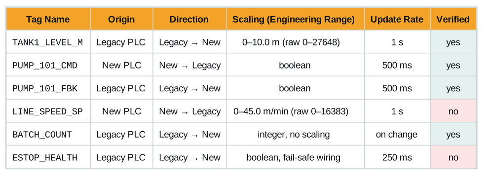
Verify each tag-list value against the field device; a reading on the gateway’s diagnostic page alone is not enough. That is what the Verified column tracks. Note also that ESTOP_HEALTH appears here only as a status echo. It is not a safety signal crossing the boundary, and you must not treat it as one.
Cutover Planning
Start in shadow mode. In shadow mode, the new controller monitors the same field devices as the legacy PLC through interposing relays or parallel terminals. The legacy system stays in control. Run shadow mode for at least one full production week. Include every product recipe and abnormal event you can reasonably provoke, such as a planned trip, startup, or changeover. During shadow running, compare the new PLC’s computed outputs against the legacy PLC’s actual outputs continuously. Most divergences trace back to a bug, a scaling error, or one of those undocumented interlocks from the inventory phase, but some come from wiring or hardware, and you find all of these while the plant doesn’t care.
Staged commissioning takes control area by area rather than all at once. A typical sequence is one noncritical loop first, then a production area, then the shared or upstream equipment last. Each area gets its own acceptance check before the next one moves. Staged cutover requires the parallel or bridge architecture from the first decision. A big-bang replacement in a single shutdown can be the right call for a simple system with a generous window. For anything with more than a few dozen I/O points and a live production schedule, staged is usually the lower-risk path. Staged cutover also means keeping both the legacy and new logic current until the last area moves over, which can add a substantial amount of engineering hours, and how many depends on how well the team documented the legacy logic.
Write rollback criteria before you start. Decide in advance, in writing, what triggers going back to the legacy system. If nobody does, you will end up arguing about it at 2 a.m. with the line down. Triggers are an output divergence in shadow mode that nobody can explain within some bounded effort, a failed area acceptance check, or an elapsed-time limit on the maintenance window. The rollback path itself has to be physical, not just a plan. Legacy wiring disconnected for a staged cutover needs to be re-connectable. That means labeled, documented, and, if you used interposing relays, reversible by moving jumpers, not by rewiring.
Commissioning Checks
Check grounding differences between old and new cabinets. Legacy panels and modern controllers frequently arrive with different grounding philosophies, such as bonded vs. floating analog returns and different shield termination practices. Connect the analog references without checking first, and ground loops can put noise on every analog input the new card reads. Check the grounding scheme of both cabinets during design, not during loop checkout.
Some interlocks exist only in legacy ladder logic. Despite a thorough inventory, some conditions hide in rungs nobody traced, such as a permissive buried in a subroutine or a fault reset gated on a timer. They surface as unexplained differences during shadow mode or, worse, as unexpected behavior on the first shift after cutover. This is the strongest argument for the shadow-running week. Shadow running can expose these differences before cutover.
Further Reading
- OPC UA Online Reference — specifications for OPC UA services, including information models and mappings.
- OPC Foundation: OPC UA architecture — overview of OPC UA capabilities, security, information modeling, and communication mechanisms.
- IEC 62541-6:2025, Mappings — mapping between OPC UA security, services, data structures, and network protocols.
- Modbus specifications — protocol specifications from the Modbus Organization.
- NIST SP 800-82 Rev. 3, Guide to Operational Technology (OT) Security — OT security guidance.