
Migrating PLC-5 to ControlLogix Without Changing Required Machine Behavior
A practical guide to converting PLC-5 logic to ControlLogix while preserving required machine behavior through architecture review and equivalence testing.
A successful project verification doesn’t prove that a converted controller will behave like the PLC-5. Rockwell Automation’s conversion manual notes that Logix Designer Export creates a syntactically correct import/export file, but may not preserve the original application’s intent. Instruction precedence, indexed addressing, and I/O addressing can all change how the converted logic behaves. Studio 5000’s online help also advises engineers to inspect and test converted logic after successful verification.
The conversion tools translate logic, but they do not establish behavioral equivalence. Use the output as a starting point. Identify the machine behaviors that must remain unchanged, then test them.
Exporting from RSLogix 5 or RSLogix 500
In RSLogix 5 or RSLogix 500, open File > Save As, then choose Logix Designer Files (*.ACD). Before exporting:
- Use Tools > Delete Unused Memory and Tools > Database > Delete Unused Addresses to remove unused memory and addresses. Removing them makes the converted project smaller.
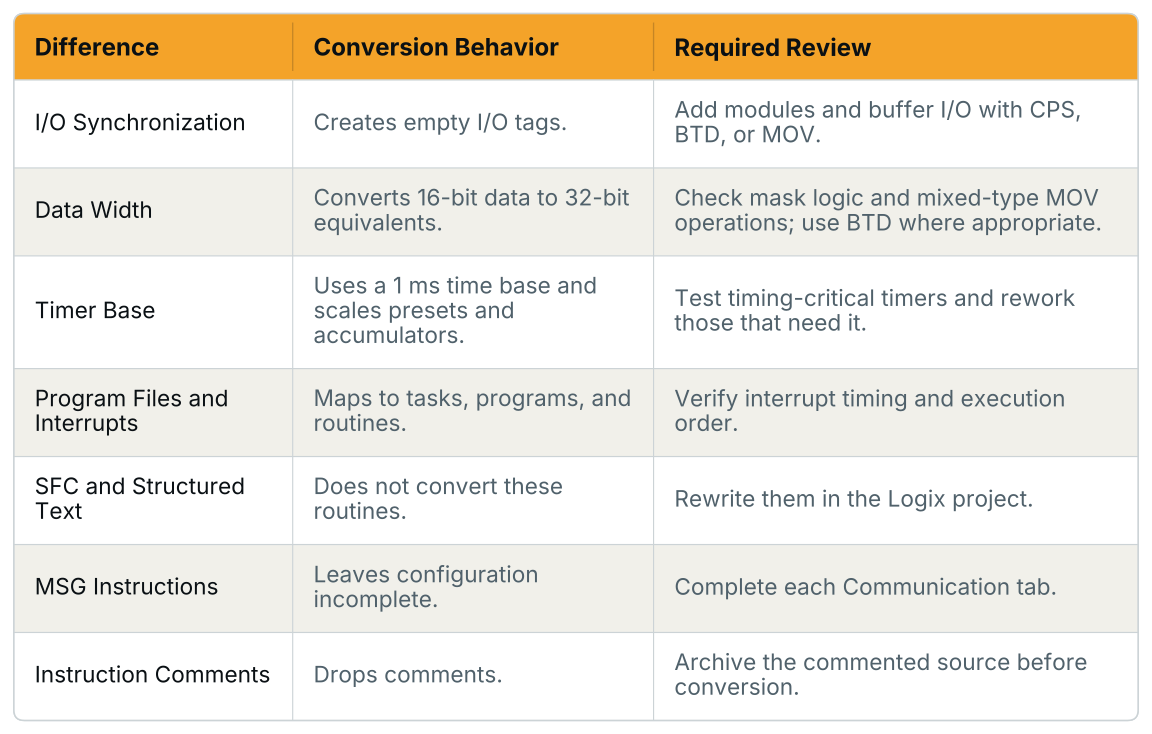
- Delete SFC and STX routines before export. The export converts ladder instructions, SFC and structured-text files must be rewritten in the Logix project.
For the export, choose the controller family (ControlLogix or CompactLogix), catalog number, firmware revision, Logix revision, and I/O migration strategy. Keep Existing I/O adds a bridge device so the Logix controller can scan the legacy I/O. Update All I/O configures the project for current 1756 or 5069 I/O families; Rockwell identifies this as its preferred option.
Review the converted project for these issues:
- Possible Conversion Error (PCE) instructions: the tool inserts a PCE instruction in a rung when it identifies a possible conversion problem. Each PCE has a comment beginning
*** Generated by Translation Tool:. A comment might read, “Source and destination types may differ.” Check the rung’s logic, correct any conversion problem, and remove the PCE. Find PCEs with Logic > Verify > Controller; the error list shows them. Double-click an entry to open its rung. - The conversion marks PLC-5 instructions with no Logix equivalent as UNK. Implement the required logic in Logix for each one, then remove the UNK.
- The tool leaves MSG configuration for you to complete. Configure each MSG on the Communication tab in Logix Designer.
- The conversion drops instruction comments. If the RSLogix 5 project is the only record of them, save a commented printout before conversion.
Architecture and Runtime Behavior
The conversion tool maps the legacy architecture to Logix structures, but the generated project still needs review for machine behavior. Review each difference below against the machine’s operating requirements.
I/O synchronization: A PLC-5 updates its I/O image tables with the program scan, so all rungs in that scan use the same input-image values. Logix reads I/O independently of the logic scan. An input can change during a scan, so separate rungs may read different values.
For physical I/O, the conversion leaves empty tags. Once the I/O modules are in the project, add instructions to copy module data into the converted I and O arrays. Place these instructions at the beginning or end of the program so the logic reads a buffer that is not refreshed while it executes. Use CPS when copying consecutive groups of data. For example, the manual shows a copy from Local:1:I.Data[0] to I[0] with a length of 8. BTD handles bit mapping; MOV copies individual elements. Without buffering, timing-sensitive logic may behave differently, including seal-in circuits, one-shot edge detection, and logic that reads the same input more than once in a scan.
PLC-5 uses 16-bit data; Logix uses 32-bit data. The change in data width can alter how converted mask instructions behave. The manual notes that MOV operations with mixed data types can affect the sign bit; the high-order bit may then be set incorrectly. BTD accounts for the bit offset when mapping INT data into DINT structures.
Logix timers use a fixed 1 ms time base. For a PLC-5 timer with a 0.01-second time base and preset 20, the tool sets the converted preset to 200. Check converted timers against the required timing and rework them if the preset no longer matches. Test timers in timing-critical paths.
Tasks and interrupts. Logix maps PLC-5 program files and interrupt structures (STIs, DIIs, PIIs, and MCPs) into its task and routine model. Interrupt-driven logic can have different execution semantics. An STI’s guaranteed periodicity does not map one-to-one to a Logix periodic task’s scheduling behavior. Verify the required timing and execution order.
The tool converts file-based addresses to arrays. For example, N7:500 becomes N7[500], and I:002 becomes I[2]. Check whether any downstream system still polls the old addresses directly; an HMI polling integer files is one example.
Capturing Required Behavior Before Conversion
Before converting an inherited machine, record the behaviors the new controller must retain. Observe the PLC-5 during operation. Trend critical analog loops and capture sequence-of-events data during startup, changeover, and fault conditions. Review alarm and fault history if it is retained by the HMI or SCADA system. Ask operators about workarounds they rely on, and determine whether those workarounds reflect required behavior.
Decide whether the legacy HMI will remain. If it polls PLC-5 integer files directly, either preserve the data and addressing map it expects or migrate the HMI as part of the project. Include this decision in the behavior baseline because it affects the migration scope.
Verifying Equivalence and Cutting Over
Derive acceptance tests from the recorded trends and startup, changeover, and fault scenarios. Test the converted logic against those scenarios before scheduling downtime. Resolve every PCE and UNK, complete the MSG configurations, and confirm that I/O buffering provides the behavior required by the machine.
With Keep Existing I/O, the export adds a bridge device so the Logix controller can scan the legacy I/O. This can support a phased migration when replacing all I/O during one outage is not feasible. Before using this approach, confirm that the selected bridge hardware and its latency meet the application’s requirements using current Rockwell documentation.
Further Reading
- Rockwell Automation, Converting a PLC-5 or SLC 500 Logic to Logix-Based Logic (1756-RM085) — The manual covers the Logix Designer Export workflow, PCE messages, and post-conversion tasks.
- Rockwell Automation, Convert a PLC-5/SLC program to ControlLogix (Studio 5000 Logix Designer Online Help) — Conversion workflow and verification guidance.
- Rockwell Automation, PLC-5 Migration — Migration services and hardware modernization options.
- Rockwell Automation, RSLogix Project Migrator Overview (MIGRAT-PP003) — Standalone utility for RSLogix 5/500 export files.
- Rockwell Automation, Migration Tools — Tools for PLC-5 and SLC 500 migrations to ControlLogix or CompactLogix.