
A Systematic Approach to PLC Troubleshooting and Maintenance
An evidence-driven workflow for isolating discrete PLC I/O faults, verifying repairs, documenting findings, and improving preventive maintenance.
A fault that looks like a PLC software problem often starts with an electrical issue at the physical layer. A loose terminal, a degraded connection, a field device that no longer switches, a module that stopped transferring signals to the processor. Swapping hardware before testing may not fix the fault and can extend downtime.
This workflow covers physical-level troubleshooting of discrete I/O. Choose the next test based on the evidence from the current stage. Prove the input, prove the signal path, prove the output, and replace hardware only when a measurement points at it.
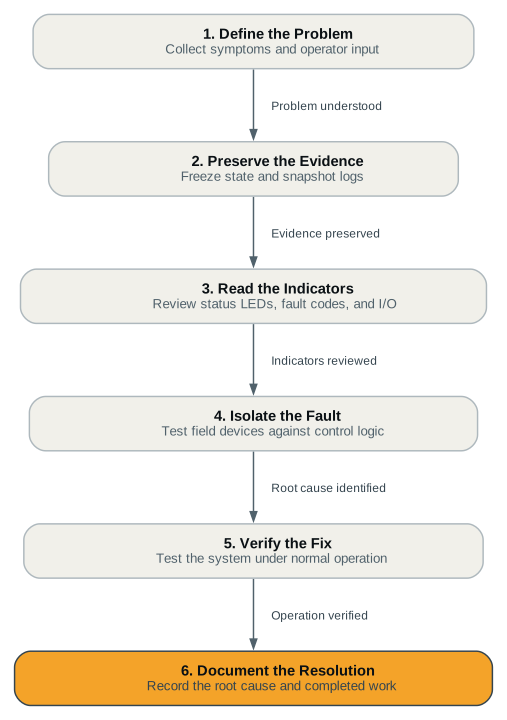
Define the Problem in Observable Terms
“The conveyor is faulty” doesn’t say which signal changed or what state was expected. The Ready input going false while the loading station should have remained ready provides a specific signal and expectation for investigation. Write the symptom in terms of what signal changed, what should have happened instead, and how you know. Note where the signal change was seen or recorded. A stale HMI value may not show when the signal changed; a timestamped event record does. When the operator is recalling the event from memory instead of working from a record, mark the account as a reported observation.
Begin by looking over the wiring and other components before reaching for a meter. Look for frayed wiring, damaged insulation, loose terminations, and corrosion. Cable types and lengths should meet specifications, and signal cabling should run separate from power conductors. Faults often show up here, before any measurement is taken.
The useful outcome of this stage is a narrower problem statement. Establishing that the controller’s value is valid and only the HMI display is stale moves you from a communication investigation to an HMI-binding investigation, with nothing replaced.
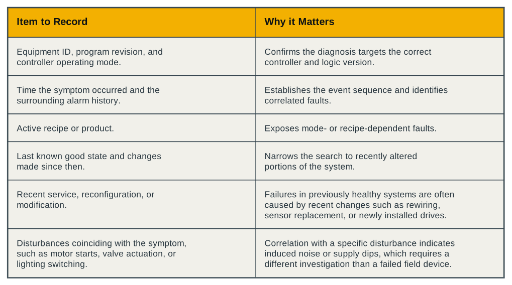
Preserve Diagnostic Evidence
Capture volatile data before resetting or cycling power: controller fault logs, diagnostic registers, buffer contents, and the exact LED states on the CPU and I/O modules. A power cycle can clear the fault codes that identify the failed circuit.
Before opening a panel or probing a circuit, use the site’s isolation and lockout/tagout procedures. If a test requires a live machine, site procedures determine what you may touch. A production machine may not fail again on demand, so the triggering condition can be difficult to reproduce. If the fault doesn’t recur during observation, record that. Don’t mark a test “passed” unless it exercised the triggering condition.
Reading the Indicators
Compare LED states to narrow the fault location; don’t read each indicator in isolation. Many I/O modules have two indicators that distinguish a field-side problem from a module-side one. Read them together.
A lit power LED on an input module can indicate that the field device is energized and its signal has reached the module. If the signal reaches the module, the logic LED should show whether its circuitry recognizes it. If the module’s documentation assigns this meaning to the LEDs, power lit with logic dark may indicate that the signal is reaching the module but is not being transferred internally. That leaves the module’s logic circuitry or optical isolator as the suspect. When the device actuates and neither light comes on, look upstream instead, at the field device, the wiring, or the supply voltage.
For an output module, start with the logic LED: it shows whether the processor has commanded the output ON. The power LED, or the blown-fuse indicator where one is fitted, shows whether the output side is switching or fed. Logic ON with power dark means the module received the command but isn’t delivering it, so check the fuse and the module. Both lit but the load not energizing means the problem is downstream in the wiring or the field device.
Manufacturers assign LED labels and meanings differently, so confirm them in the module documentation. LEDs are also preliminary signs only. They cannot diagnose every failure mode, and that is where the measurement stage comes in.
Isolate the Fault on Inputs
For an input that doesn’t register, trace the signal from the field device through the input module to the processor’s image table, which stores input states. Test the input path first, since that separates an input hardware fault from a program-logic fault.
Place the PLC in a mode that reads inputs but doesn’t drive outputs, such as standby or test mode. Then manually actuate the field device; for example, close a limit switch by hand. Note whether the module’s power LED is lit; it confirms the module is powered, but says nothing about wiring continuity or whether the input signal has reached the channel. Then check the input status in the controller: in test mode, the image table bit for that input should go to 1, or the contact instruction should highlight in the programming display. A correct input reading shifts the search to the program logic; the field device and input path have passed this check. If the module has power but the image-table bit stays off, look at the channel wiring and configuration before blaming the module.
An unlit power LED alone can’t tell you whether the fault is in the field circuit. Keep the field device actuated and put your meter leads on the input module terminal. What you see there sorts the remaining cases. Nominal voltage at the terminal (120 VAC on a 120 VAC input, for example) means the signal has reached the module. If the module doesn’t register it, the module itself is the likely fault. When the reading comes in 10–15% below nominal, look for signal loss upstream, starting with the source voltage feeding the field device. That threshold is a rule of thumb from training material, not a universal specification. Use the module documentation to find the input-recognition threshold. A zero reading leaves the wiring and field device as the next places to check.
To split the remaining path, measure voltage across the field device with it activated. No voltage on the load side, the terminal feeding the module, means the device is faulty. The device is receiving power but not switching the signal through. Voltage present at the device but not at the module means the wiring between them is the problem. Check the wiring and its terminations at junction boxes and terminal blocks. Measuring at midpoints of the signal path like this halves the remaining search space with each measurement, which is why a meter beats part-swapping.
Before condemning anything, back up the voltage measurements with resistance and continuity checks on the wiring run. Check continuity, compare resistance with the specification for the cable length, and verify that the wiring and shields are isolated from one another and from ground. For shielded cable, check that the shield is grounded as specified for the installation. For analog signals it is conventionally grounded at one end only, typically the control-room side, though specific installations may differ. When cable damage is suspected, measure capacitance between the conductors and shield. The reading should match the manufacturer’s specification for the cable type and length. A value far off spec points to damage or an unintended substitution.
Isolate the Fault on Outputs and the CPU
Output troubleshooting runs the same boundary logic in reverse, from the processor’s command outward. Start by verifying the output module’s switching supply is at the correct level. In a 120 VAC system that means within roughly 10% of rated, or 108–132 VAC, again a typical training figure rather than a universal spec. Before replacing a blown fuse, compare its rating with the connected load’s current draw. A fuse that blows repeatedly indicates an overload or short on that branch, so use the schematic to identify every device on the circuit before restoring power. When the logic LED is ON but the power LED is dark, the module itself has failed. Replace the module.
With both indicators showing the expected states and the load still off, measure voltage at the output terminal. No voltage there means the module. Voltage present shifts attention to the field wiring for breaks and terminations, then to the voltage arriving at the field device with the return path confirmed. Power present and the device still unresponsive means the device itself is faulty. A direct-power test may help isolate the device, but perform it only if the device requirements and approved site procedures allow it. If it still doesn’t respond, the device is bad. If it works, the fault is in the wiring between device and module.
The CPU comes into play when multiple unrelated symptoms appear, or nothing responds at all. Check its diagnostic indicators (power OK, memory OK, communications OK) and verify the supply voltage from the transformer is adequate for all loads, with no voltage drops or blown fuses in the control circuit. If the PLC still won’t start with adequate supply voltage, check the CPU for a fault. Before removing the CPU, note whether its memory or communications indicator is lit; either one can indicate that the CPU needs replacement.
Verify and Separate Restoration from Root Cause
A swapped module that restores operation is a restoration, not a diagnosis. Before declaring the problem resolved, ask why the module failed. Repeated fuse failures point to an overload or short on the branch. If a module died soon after a motor drive was installed nearby, suspect induced noise or supply quality, because the replacement will likely fail the same way. A terminal found loose points at vibration as a cause class, not a one-off. Check the other terminals in that panel, and feed the finding into the maintenance schedule.
Verification means a full functional test against the expected behavior, not just confirming the single symptom is gone. If the original fault appeared in one recipe or operating mode, test under that condition specifically. If the fault never reproduced during your observation window, your verification is weaker. Say so in the record, and note the conditions under which the fix should be re-examined.
Document the Findings
At minimum, record the symptom as observed, the measurements taken (what, where, under what conditions), the component replaced and the evidence supporting it, the root cause found or left unresolved, and any outstanding work. If the restoration was temporary (a jumper in place of a failed interlock, for example), keep that record separate from the permanent corrective action and assign an owner to the outstanding item. Documentation is what turns this troubleshooting session into a shorter one next time, particularly for intermittent and temperature-dependent faults that only appear on someone else’s shift.
Preventive Maintenance Shrinks the Workload
Preventive maintenance reduces how often faults occur. Coordinate PLC maintenance with regular machine maintenance to minimize downtime, setting inspection intervals according to environmental and operating conditions and adjusting them as experience dictates. Harsher environments generally call for more frequent checks.
At dusty sites, clean or replace filters as needed, and remove dust from heat sinks and circuitry. Dust can impede heat dissipation, pushing components beyond their temperature ratings; conductive dust reaching the boards can also cause permanent shorts. Periodically check plugs, sockets, terminal strips, and modules for secure connections, especially where vibration is constant. In vibration-prone environments, a vibration detector interfaced to the PLC can monitor vibration that may precede a failure.
Keep space around the PLC for airflow. Paperwork stacked on or against the rack restricts airflow, trapping heat around modules. Locate heavy equipment that generates noise away from the PLC.
Feed findings from verification into the maintenance schedule: a vibration finding may call for more frequent connection checks, while a noise finding can prompt a review of equipment placement. Over time, measurements from diagnosed faults build evidence about the installation’s failure modes, such as terminals that loosen, circuits that overload, or cable segments that degrade.
Further Reading
- IDC Technologies, Problem Solving of PLCs and SCADA Systems — training notes on PLC troubleshooting, indicator interpretation, and I/O fault isolation.
- IDC Technologies, PLC Startup and Maintenance — preventive maintenance practices and input/output troubleshooting procedures.
- Fluke Corporation, Troubleshooting Programmable Automation Controller I/O at the Physical Level (Application Note 4210771) — physical-layer inspection and measurement guidance.
- Rockwell Automation, Maintenance of Industrial Control Equipment (NEMA publication IN001) — periodic inspection intervals and environmental considerations.